How POTS Lines Work
January 28, 2026
A Technical Guide to Analog Telephone Infrastructure
The Plain Old Telephone Service (POTS) line remains a cornerstone of traditional telecommunication infrastructure, even as digital and IP-based technologies dominate modern networks. For network engineers, building managers, and IT professionals responsible for critical systems (such as fire alarms, elevators, and security networks) understanding how a POTS line is connected is essential. While many businesses have transitioned to VoIP and other digital alternatives, legacy POTS lines continue to prevail for certain applications.
In this guide, we’ll explore the technical underpinnings of POTS lines, including their wiring, network architecture, analog signal behavior, integration with networking systems, and troubleshooting.
If you’re new to POTS technology, start here: What is a POTS line?
POTS Line Infrastructure Overview
The architecture of a POTS network is deceptively simple yet meticulously engineered. POTS lines form a continuous analog path from the central office to the customer premises, traversing multiple components along the way.
Major components include:
- Central Office (CO): The hub where subscriber lines terminate. Switching equipment inside the CO routes calls across the Public Switched Telephone Network (PSTN) and provides power to subscriber lines.
- Local Loop: The physical copper line connecting the CO to customer premises, also called the “last mile.” This segment carries both voice signals and DC power.
- Customer Premises: Includes the Network Interface Device (NID), internal wiring, and telephone endpoints.
- Switching Equipment: Historically electromechanical, now often digital Class 5 switches, these devices manage call routing and connectivity between local and long-distance lines.
- PSTN Basics: The interconnected global network of switches and trunks that facilitates voice communications.
This end-to-end infrastructure ensures that POTS lines remain operational during power outages and deliver high reliability for analog voice communications.
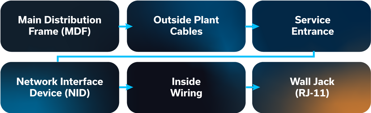
How POTS Lines Are Physically Connected
Understanding how a POTS line is connected requires tracing the path from the central office to the end-user device:
- Main Distribution Frame (MDF): The central office termination point where subscriber lines are patched into the switching system.
- Outside Plant Cables: Copper cables running overhead or underground from the MDF toward the customer location.
- Service Entrance: The point where cables enter the building, often terminating at a Network Interface Device (NID).
- Network Interface Device (NID): Provides the demarcation point between carrier infrastructure and customer wiring. Contains surge protection and test access points.
- Inside Wiring: Twisted-pair copper wires running through walls or conduit to endpoints.
- Wall Jack (RJ-11): Standard connector for telephones, fax machines, and other analog devices.
Copper Twisted-Pair Specifications
- Typically 24–26 AWG
- Pairs carry tip (positive) and ring (negative) signals
- Shielding varies based on distance, installation type, and environmental factors
Proper cable routing and protection against physical damage, water intrusion, and electromagnetic interference are critical for maintaining line quality.
POTS Wire and Cabling Specifications
The copper POTS wire is the foundation of analog telephone reliability.
Twisted-Pair Design
Reduces electromagnetic interference (EMI) and crosstalk between adjacent lines.
Two-Wire vs. Four-Wire Configurations
Most POTS lines use a single pair for bidirectional voice; four-wire lines support simultaneous duplex signaling and are used in some trunking contexts to separate transmit/receive paths.
Color Coding Standards
"Tip” is typically green/white and “Ring” is red/white, but color codes may vary. Verifying wiring standards on-site helps ensure consistent troubleshooting and maintenance.
Cable Types
- Aerial: Suspended on poles, subject to weather and environmental stress.
- Underground: Buried in conduit or direct burial cable; requires careful waterproofing.
- Indoor Premises: Low-voltage cables within walls and ceilings, following building codes.
Distance Limitations
Attenuation becomes significant over long loops (often around 18,000 feet), depending on gauge and conditions.
The Central Office and Telephone Switching
At the heart of every POTS network lies the Central Office, which serves as the critical hub for routing voice traffic. The CO terminates subscriber lines, supplies power, and manages call switching through a combination of historical and modern equipment. While early systems relied entirely on electromechanical switches, like step-by-step or crossbar switches, today’s COs are increasingly digital, using Class 5 switches that offer enhanced call routing, diagnostics, and management while maintaining backward compatibility with analog endpoints.
Key functions of the CO include:
- Call Routing: Directing local calls within the CO and connecting long-distance calls through inter-office trunks.
- Line Supervision: Monitoring subscriber lines for on-hook/off-hook status, line faults, or busy conditions.
- Power Distribution: Providing 48V DC and ring voltage to all lines, ensuring phones function even during building power outages.
- Interconnection with PSTN: Linking to other COs and regional exchanges to provide nationwide and international voice connectivity.
By centralizing these operations, the CO helps ensure that POTS lines can deliver a consistent, reliable voice signal, even as infrastructure ages or environmental factors change. Proper understanding of CO functionality is critical for technicians performing troubleshooting or upgrades.
How Analog Signals Work on POTS Lines
The reliability of analog POTS lines stems from their simplicity in transmitting voice signals as continuous electrical waveforms. Analog signals use variations in voltage amplitude to represent the air pressure fluctuations of human speech, operating over a frequency range of 300–3,400 Hz.
The process works as follows:
- Conversion of Voice to Electrical Signals: The telephone microphone converts sound waves into proportional electrical signals.
- Transmission Over Copper Pairs: These signals travel through twisted-pair copper wiring, which minimizes interference and crosstalk.
- Amplitude and Frequency Modulation: Amplitude variations correspond to audio amplitude within the voice band.
- Reception and Conversion: At the receiving end, the speaker converts electrical signals back into audible sound.
Signal quality can be affected by line length, wire gauge, and environmental interference. Despite these limitations, analog transmission remains robust, delivering clear voice communication without dependency on internet connectivity or local power, a key reason why critical systems still rely on POTS.
POTS Line Power: How the Phone Gets Electricity
A unique advantage of POTS lines is their integrated power delivery. Unlike VoIP phones that rely on building electricity, POTS handsets receive power directly from the CO, enabling functionality during local outages.
- 48-Volt DC Supply: Constantly delivered along the same copper pair used for voice, sufficient to power basic telephone functions.
- Ring Voltage: Approximately 90V AC pulses superimposed on the line to activate the ringer for incoming calls.
- Battery Backup at CO: Central offices maintain batteries and sometimes diesel generators to ensure continuous line operation during wider power failures.
- Line Loading: Each line contributes to total CO power load; proper engineering ensures even long subscriber loops remain within operational limits.
Because of this integrated power supply, POTS lines remain some providers’ choice for life-safety systems, elevator phones, and other applications where operational continuity is critical.
POTS in Networking Environments
Even though POTS is an analog system, it often coexists with modern digital networks, particularly in businesses that maintain legacy systems while adopting IP-based communications. Integrating POTS into networking environments requires understanding how analog signals can interface with digital infrastructure.
Key integration methods include:
Analog Telephone Adapters (ATAs)
These devices convert the analog signals from a POTS line into digital IP packets, allowing traditional phones to operate over VoIP networks. ATAs maintain POTS functionality while enabling centralized network management, call routing, and monitoring.
Channel Banks and Multiplexing
Businesses with multiple POTS lines have historically aggregated them into digital T1 or E1 circuits using channel banks. Multiplexing allows multiple analog lines to share a single digital pathway, reducing cabling and simplifying interconnection with digital PBX systems.
PBX and Key System Integration
Private Branch Exchange (PBX) and key telephone systems can interface directly with POTS lines or convert them for VoIP integration. This enables hybrid setups where offices can maintain analog endpoints for critical systems while modernizing internal communications digitally.
Hybrid Networks
Many organizations adopt a hybrid strategy: POTS lines for fire alarms and elevator phones, and VoIP for general office communications. This balances the reliability of traditional lines with the flexibility of modern networking.
POTS integration requires attention to line voltage, impedance matching, and proper network termination. Inadequate integration can cause call quality issues, signal degradation, or even equipment failures. Network administrators need to ensure that analog endpoints receive consistent power and that any conversion devices are correctly configured to avoid latency or echo.
POTS Modems and Data Transmission
Beyond voice, POTS lines historically supported low-speed data transmission, which was a critical bridge before widespread broadband. Analog signals could be modulated to carry digital data using frequency-shift keying (FSK) or similar techniques.
Key applications include:
- Dial-Up Internet: Early internet connections relied on POTS lines, with modems converting digital computer signals into audio tones suitable for analog transmission. Maximum speeds peaked at 56 Kbps.
- Fax Machines: Functioning essentially as modems, fax machines convert scanned images into audio frequencies sent over POTS lines. Reliability of POTS was crucial to consistent fax delivery.
- DSL Overlay: Digital Subscriber Line (DSL) technology allows higher-frequency data signals to coexist with voice on the same copper pair, effectively transforming a POTS line into a high-speed internet conduit without disrupting voice service.
Understanding these data applications is essential for businesses maintaining hybrid analog-digital environments or migrating legacy systems, particularly for remote monitoring devices, telemetry, or low-bandwidth IoT endpoints.
Signaling and Call Control on POTS Lines
The simplicity of POTS disguises a complex signaling architecture that helps support accurate call setup, monitoring, and termination:
- On-Hook/Off-Hook States: Indicates line availability. Off-hook signals the CO to provide dial tone.
- Dial Tone Generation: The CO sends a steady tone when the line is ready to accept input.
- Dual-Tone Multi-Frequency (DTMF) Signaling: Each key press generates a unique pair of tones corresponding to a number or symbol, enabling accurate dialing.
- Rotary Pulse Dialing (Historical): Mechanically interrupts the line current to encode digits, still supported in some legacy systems.
- Ring Signal: AC pulses (~90V) alert the phone of incoming calls.
- Call Progress Tones: Busy signals, fast busy, reorder tones, and others inform users of network status.
- Supervision and Disconnect: Helps the CO detect when a call ends to free the line for new connections.
Understanding POTS signaling is essential for configuring ATAs, PBXs, and hybrid systems. For example, an improperly configured ATA may fail to recognize on-hook/off-hook status, causing dropped calls or missed alarms.
POTS Line Connection for Different Systems
POTS lines are versatile, capable of connecting to a wide variety of devices and systems beyond a standard telephone. Understanding how these connections are made supports reliability, compliance, and seamless integration, particularly in environments where mission-critical operations depend on continuous connectivity.
Standard Telephone Connections
The most common use of a POTS line is for traditional analog phones. A single twisted pair of copper wires (tip and ring) connects the phone to the wall jack, which interfaces with the building’s internal wiring and ultimately the service provider’s network. Proper installation includes verifying polarity, ensuring secure termination at both the Network Interface Device (NID) and the handset, and routing cables to minimize interference.
Fire Alarm Systems
Fire alarm panels rely on POTS lines for continuous monitoring and reporting to central stations. Connections are made through the panel’s dedicated telephone interface, which supervises line activity to detect faults such as line cuts or power failures. Maintaining a stable POTS connection is critical because any disruption could prevent alarms from being reported. In modern deployments, many organizations also use hybrid approaches, pairing POTS with cellular backup for redundancy.
Elevator Emergency Phones
Elevator emergency communication systems are regulated under ASME A17.1 and typically require POTS connectivity due to its reliability during power outages. The connection mirrors that of a standard phone but is often routed through a dedicated, hardened line with backup power to ensure the phone remains functional under all conditions. Using POTS supports compliance while providing emergency responders with a dependable communication link.

Fax Machines and POS Terminals
Though less common today, fax machines and credit card terminals still rely on POTS for data transmission. These devices connect through standard RJ-11 jacks or dedicated analog ports on multi-line PBX systems. Proper line configuration, including isolation from electrical interference, is crucial to prevent failed transmissions or data corruption.
Security Systems
Many security systems, including intrusion alarms and monitoring sensors, utilize POTS lines to communicate alerts to monitoring centers. Connections are typically hardwired through the system’s control panel to support constant supervision. Regular testing of these lines is necessary to comply with safety standards and to verify the integrity of the connection.
Multi-Line Configurations
In offices or facilities requiring multiple analog endpoints, POTS lines can be aggregated through PBX or key systems. These systems manage routing, line allocation, and call distribution while maintaining the reliability inherent to POTS. Correct configuration helps ensure that each line functions independently while allowing centralized control.
By understanding how a POTS line connects across various systems, from phones to alarms, elevators, and point-of-sale devices, technicians and facility managers can better support both operational continuity and regulatory compliance.
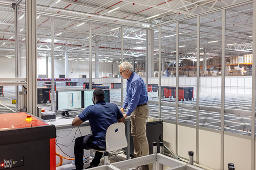
Testing and Troubleshooting POTS Line Connections
Ensuring that a POTS line is correctly connected and functioning is critical for both everyday communications and mission-critical systems like fire alarms and elevator phones. Proper testing and troubleshooting practices help maintain reliability, minimize downtime, and prevent costly disruptions.
Continuity and Voltage Testing
The first step in testing a POTS line is verifying continuity from the central office to the endpoint device. This involves using a line tester or multimeter to check that the copper wires are intact and free from breaks. Voltage testing is equally important; POTS lines typically carry around 48 volts DC from the central office, which powers the phone even during a local power outage. Any significant voltage drop may indicate a wiring fault or excessive line loading.
Tone and Probe Methods
Technicians often use a tone generator and probe to trace POTS wires through walls, conduit, or distribution frames. The tone generator sends a signal down the line, which the probe detects at the other end. This technique is invaluable when identifying misrouted or disconnected wires, especially in multi-line installations or older buildings with complex internal wiring.
Common Connection Problems and Solutions
Despite the reliability of POTS, lines can experience a variety of issues. Understanding these problems and their solutions can ensure quick restoration of service:
| Connection Problem | Solution |
|---|---|
| Open Circuits: Occur when a wire is broken or disconnected. | Inspect terminations at both the NID and device, repair or replace the wire as needed. |
| Short Circuits: Happen when tip and ring wires touch, causing the line to fail. | Identify the fault location using a multimeter and separate or replace affected wires. |
| Ground Faults: Caused by a wire contacting a conductive surface, introducing unwanted current paths. | Check insulation and grounding, isolate faulty wiring. |
| Cross-Talk: Electrical interference between adjacent lines can cause static or audio issues. | Maintain proper wire separation, use twisted-pair wiring, and check for cable damage. |
| Noise and Interference: Sources include electrical equipment, fluorescent lights, or poorly shielded cables. | Re-route wires, add ferrite cores, or replace degraded cables. |
Step-by-Step Troubleshooting Process
- Visual Inspection: Start with a thorough inspection of wiring, connectors, and jacks.
- Check Line Voltage: Confirm DC voltage and ring voltage are within acceptable ranges.
- Test Continuity: Use a multimeter or line tester to verify an unbroken path.
- Trace the Line: Use tone and probe methods for multi-line or long-distance installations.
- Address Faults: Repair open circuits, shorts, or ground faults as identified.
- Verify Functionality: Test with a phone, alarm panel, or endpoint device to help ensure proper operation.
- Document and Monitor: Record findings and perform periodic checks to prevent future issues.
Regular testing and proactive troubleshooting keep POTS lines dependable, which is especially crucial for systems where failure is not an option.
Limitations of POTS Line Technology
While POTS lines have provided decades of reliable service, the technology comes with inherent limitations that increasingly impact businesses and organizations relying on critical communications. Understanding these constraints is key to planning upgrades or replacement solutions.
Distance Limitations
POTS lines rely on copper twisted-pair wiring to transmit analog signals from the central office to the customer premises. Over long distances, signal quality deteriorates, limiting reliable reach without the use of repeaters or amplifiers. For organizations with large campuses or remote facilities, this can lead to degraded call quality, weak dial tones, or intermittent connectivity.
Bandwidth Constraints
POTS was designed for basic voice communications. Its bandwidth is limited to the standard 300–3,400 Hz frequency range, sufficient for human speech but inadequate for high-speed data. As businesses increasingly rely on data-intensive applications, including internet-connected security systems and monitoring devices, the low bandwidth of POTS lines becomes a significant bottleneck.
Scalability Challenges
Adding lines to a POTS network requires new physical copper wiring, coordination with local telephone carriers, and often expensive infrastructure upgrades. This makes expansion cumbersome, slow, and costly compared with digital or IP-based alternatives. Organizations with growing communications needs may find scaling POTS systems impractical.
Maintenance Complexity
Copper lines require ongoing maintenance, including corrosion prevention, testing, and repair of physical wiring. Older infrastructure may experience issues like cross-talk, interference, or broken connections that need frequent attention. This maintenance overhead increases operational costs and can lead to unexpected downtime.
Aging Infrastructure
Many POTS networks rely on decades-old copper infrastructure, including legacy switching and distribution infrastructure. As carriers retire legacy systems and phase out copper services, relying on POTS lines exposes organizations to service interruptions, higher fees, and difficulty sourcing technical support or replacement parts.
For organizations seeking reliable, scalable, and future-ready communications, these limitations highlight the need to explore modern alternatives.
Moving Beyond POTS Technology
Transitioning away from POTS technology enables businesses to modernize their communications infrastructure while maintaining reliability for critical systems. Modern replacement solutions, ranging from cellular-based options to VoIP and fiber networks, offer enhanced scalability, monitoring capabilities, and compliance with regulatory requirements.
Organizations moving beyond POTS can expect improved reliability, scalability, enhanced features and future-proof infrastructure. INS provides expertise in planning and executing POTS replacements, helping organizations migrate seamlessly while maintaining uninterrupted service for critical systems.
For a full overview of modern options, see our POTS line replacement solutions and learn how INS can guide your transition.